Introduction
In robotics, the quality of data-gathering pipelines directly impacts the performance of downstream learning algorithms. Whether training Diffusion Policies, Action Conditional Transformations (ACT), or reinforcement learning models, smooth and consistent control data is essential.
This blog presents a control framework designed to provide stable and high-quality data for learning. By combining velocity control, delta pose representations, and null-space optimization, the system ensures consistent and noise-free data collection, enabling effective training for complex robotics tasks.
1. Choosing the Right Control Method: Position vs. Velocity Control for Robots
When designing robotic systems, the choice of control method significantly impacts motion quality and task execution. Stability and smoothness are paramount considerations, as they directly affect both the robot's performance and the reliability of data collection for learning algorithms. Velocity-based control often provides superior stability compared to position control, especially in scenarios requiring fluid motion and precise interaction with the environment. This advantage stems from velocity control's inherent ability to maintain smooth transitions and reduce abrupt movements that could introduce unwanted oscillations or jerky behavior. For robotics applications where consistent, predictable motion is essential - such as in collaborative robots or precision manufacturing - the smoother response characteristics of velocity control can lead to more reliable operation and better data quality for machine learning implementations.
1.1 Position Control: Understanding Sources of Instability
Position control in robotics typically employs PD (Proportional-Derivative) control, where the controller calculates position adjustments based on current state and desired velocity. However, inherent forward kinematics estimation errors can lead to instability, particularly at high control frequencies. The control process can be described as follows:
where:
- \(\Delta \mathbf{x}(t)\): Computed position adjustment
- \(\mathbf{K}_p\): Proportional gain matrix
- \(\mathbf{K}_d\): Derivative gain matrix
- \(\mathbf{x}_{\text{des}}\): Desired position
- \(\mathbf{x}_{\text{cur}}\): Current position
- \(\dot{\mathbf{x}}_{\text{des}}, \dot{\mathbf{x}}_{\text{cur}}\): Desired and current velocities
- \(FK(\mathbf{q})\): Forward kinematics function
- \(\epsilon\): Forward kinematics estimation error
The instability arises from the continuous accumulation of forward kinematics errors. At each control cycle (typically 100-200Hz), the controller computes a position adjustment \(\Delta \mathbf{x}(t)\) based on the estimated current position. However, since \(\mathbf{x}_{\text{actual}}\) always differs from \(\mathbf{x}_{\text{estimated}}\) by some error \(\epsilon\), the controller perpetually tries to correct for this difference. This leads to a cascading effect where:
At high control frequencies, these accumulated errors manifest as oscillations, as the controller continuously overcompensates for estimation errors. The higher the control frequency, the more rapid these oscillations become, potentially leading to significant instability in the system.
1.2 Velocity Control: A More Stable Approach
Velocity control achieves smoother motion by directly regulating the rate of change rather than absolute position. The key difference is that velocity control uses the instantaneous motion state, which is less sensitive to accumulated forward kinematics errors. The control law can be expressed as:
where:
- \(\mathbf{v}_{\text{cmd}}(t)\): Commanded velocity
- \(\mathbf{K}_p\): Position gain matrix (for correction)
- \(\mathbf{K}_d\): Velocity gain matrix
- \(\Delta t\): Control cycle time interval
The stability advantage of velocity control comes from three key factors:
1. Integration Effect: Since the position is achieved through velocity integration (\(\int \mathbf{v}_{\text{cmd}}(\tau) d\tau\)), the system naturally smooths out high-frequency disturbances. Even if there are forward kinematics errors \(\epsilon\), they don't accumulate in the same way as position control:
2. Error Damping: When using velocity control, any instantaneous error in position estimation affects only the current velocity command, rather than creating a direct position adjustment. This means that estimation errors result in velocity adjustments that are inherently bounded by the integration process:
3. Natural Motion Constraints: Velocity control inherently respects the physical limitations of the robot's motion capabilities. Even with aggressive position error corrections, the commanded velocities remain within achievable limits, preventing the rapid oscillations seen in position control.
2. Delta Pose Representations in Teleoperation and Learning
Our teleoperation and data gathering framework employs two distinct types of delta poses:
- Teleoperation Delta Poses: Ensure consistency and frame independence when mapping VR controller movements to robot actions
- Learning Delta Poses: Serve as the action space for learning algorithms, enabling better mapping between observations and actions in the robot's base frame
Now let's examine each type in detail.
2.1 Delta Pose in VR Controller Frame and Frame Transformation
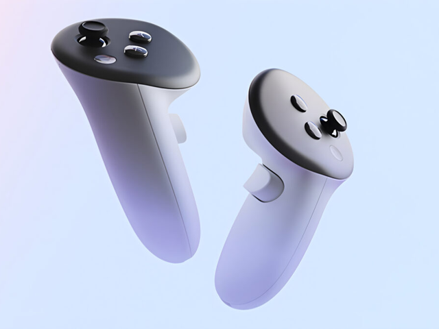
When teleoperating the robot using a VR controller, we need to map the controller's motion to the robot's end-effector. The VR controller's pose is tracked in the VR headset's coordinate frame, typically with z-up convention, while the robot's end-effector pose is defined in the robot base frame, often using z-up or z-forward conventions depending on the manufacturer. This mapping involves careful transformation between these coordinate frames to preserve the operator's intended motion.


The delta pose represents the relative pose change between consecutive timesteps in a frame's local coordinate system. By working with delta poses rather than absolute poses, we free the operator from needing to synchronize their hand position with the robot's current state. Furthermore, expressing the delta pose in the frame's own coordinate system makes our approach independent of both the VR system's and robot's base frames, enabling flexible positioning of both systems.
Delta Pose Computation:
First, we compute the delta pose in the VR controller frame between timesteps t-1 and t:
$ \Delta T_t^c = \left( T_{t-1}^c \right)^{-1} T_t^c $This transformation matrix can be decomposed into rotation and translation components:
$ \Delta T_t^c = \begin{bmatrix} \Delta R_t^c & \Delta p_t^c \\ 0 & 1 \end{bmatrix} $Frame Transformation:
To transform this delta pose to the end-effector frame, we use a fixed transformation matrix \(R_{ve}\) that accounts for the difference in coordinate conventions between the VR controller and robot end-effector frames:
$ \Delta R_t^e = R_{ve} \Delta R_t^c R_{ve}^T $ $ \Delta p_t^e = R_{ve} \Delta p_t^c $This formulation provides three significant advantages that make it particularly suitable for practical robotic teleoperation:
First, it enables asynchronous operation by tracking relative changes rather than absolute positions. In traditional teleoperation systems, operators must carefully align their initial hand position with the robot's current end-effector pose. Our delta-pose approach eliminates this requirement - operators can begin from any comfortable position, and the system will track their relative motions, significantly reducing setup time and operator fatigue.
Second, the frame independence property of delta poses allows arbitrary positioning of both the VR system and robot. Since the motion is computed relative to the controller's own frame rather than any global coordinate system, the VR headset can be placed anywhere in the workspace without affecting the control mapping. This also makes the system robust to tracking drift in the VR system, as small errors in absolute position tracking don't accumulate in the relative motion calculations.
Third, by encoding the coordinate convention differences in \(R_{ve}\), this approach provides strong cross-embodiment compatibility. The transformation matrix \(R_{ve}\) serves as a simple interface between different robot platforms, only accounting for fundamental differences in coordinate conventions (such as z-up versus z-forward). This means the same VR control system can be rapidly deployed across different robot platforms by simply updating \(R_{ve}\), from industrial arms to mobile manipulators.
Together, these properties - asynchronous operation, frame independence, and cross-embodiment compatibility - create a robust and flexible teleoperation framework suitable for diverse real-world applications.
2.2 Base Frame Delta Pose for Learning
For learning purposes, we represent delta poses in the robot's base frame rather than the end-effector frame used in teleoperation. This choice provides better consistency for learning algorithms and handles real-world robotic limitations more effectively. The base frame representation helps address several key challenges in learning from teleoperation data.
Base Frame Computation:
Given two consecutive end-effector poses in the base frame:
$ T_t^b = \begin{bmatrix} R_t^b & p_t^b \\ 0 & 1 \end{bmatrix}, \quad T_{t-1}^b = \begin{bmatrix} R_{t-1}^b & p_{t-1}^b \\ 0 & 1 \end{bmatrix} $We compute the delta pose as:
$ \Delta T_t^b = \left( T_{t-1}^b \right)^{-1} T_t^b $Which expands to:
$ \Delta T_t^b = \begin{bmatrix} (R_{t-1}^b)^T R_t^b & (R_{t-1}^b)^T(p_t^b - p_{t-1}^b) \\ 0 & 1 \end{bmatrix} $Using base frame delta poses ensures consistent action-state relationships in the learning process. When using end-effector frame representation, the same action can result in different base-frame movements depending on the current end-effector pose, which can confuse learning algorithms. The base frame representation maintains consistency: the same movement command will produce the same base-frame delta regardless of the current robot configuration.
Real robotic systems often show discrepancies between commanded and executed movements due to PD control and physical limitations. By computing delta poses from actual robot state data, we capture these execution patterns, allowing the learning algorithm to model realistic robot behavior rather than ideal movements. This is crucial for developing policies that work well on real systems.
Additionally, teleoperation systems can produce movement outliers due to network delays and signal processing limitations. The base frame representation makes these outliers easier to handle by providing natural physical bounds based on robot capabilities. This leads to more effective data normalization, which is particularly important for learning algorithms like diffusion policies that require well-normalized input data for stable training.
3. Null-Space Optimization
For redundant robots with more degrees of freedom than required for the task, null-space optimization enables the achievement of secondary objectives without interfering with the primary task of end-effector control. This optimization is crucial for teleoperation, where we want to maintain precise control while keeping the robot in favorable configurations.
Mathematical Framework:
The differential kinematics relating task and joint velocities is given by:
$ \dot{x} = J(q)\dot{q} $The primary task solution using the pseudo-inverse provides minimal joint velocities:
$ \dot{q}_p = J^\dagger \dot{x} $The null space projector ensures secondary tasks don't affect the primary task:
$ N = I - J^\dagger J $We define a quadratic cost function for joint configuration optimization:
$ H(q) = \frac{1}{2}(q - q_{\text{home}})^T W (q - q_{\text{home}}) $The complete solution combines both tasks while maintaining hierarchy:
$ \dot{q} = J^\dagger \dot{x} + N(-W(q - q_{\text{home}})) $3.1 Benefits of Null-Space Optimization
This optimization framework provides several crucial advantages for teleoperation:
- Task Hierarchy: The null-space projector ensures that secondary objectives never interfere with end-effector control, maintaining precise teleoperation.
- Joint Limit Avoidance: Secondary tasks can keep joints away from their limits, ensuring smooth and safe operation throughout the workspace.
- Optimal Configuration: The robot maintains high manipulability by optimizing its joint configuration, improving dexterity during complex tasks.
- Efficient Motion: By minimizing joint movement through the home configuration cost, we reduce system wear and energy consumption.
Conclusion
By combining velocity control, delta pose representations, and null-space optimization, this framework provides a robust solution for data-gathering in robotics. The resulting data is smooth, consistent, and suitable for modern learning algorithms, paving the way for intelligent and adaptive robotic systems.